
Migration from manual crankshaft alignment to servo-controlled station — measurement noise from 120 µm to 7 µm
The previous process was manual: measure run-out with a dial indicator, mark the high point with a marker, strike with a hard polymer hammer, and repeat 3 or 4 times. Up to 6 minutes per part. And a metrological problem the client didn't know about: the manual system had more noise than tolerance.
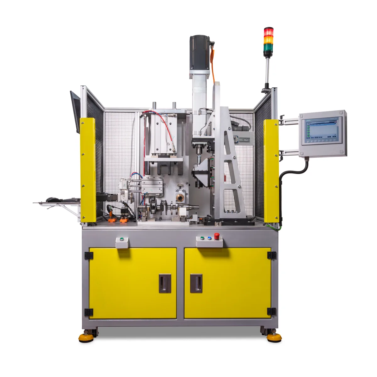
The manual system had more noise than tolerance
The previous process was entirely manual and operator-dependent: measure the run-out of the crankshaft taper with a dial indicator, mark the high point with a marker, take the part to a fixture, strike with a hard polymer hammer, measure again. If not in spec, repeat 3 or 4 times. Up to 6 minutes per part if the assembly arrives with 200–300 µm of initial deviation.
But the more serious problem was metrological and the client didn't know it: the indicator, resting on the tapered geometry without limiting axial movement of the assembly, read 120 µm of noise — when the product tolerance is 80 µm. The measurement system guaranteed nothing.
Metrology independent of force — 4 iterations down to 7 µm
The measurement system and the force system are two independent mechanisms in the same fixture: the force chain never touches the measurement chain. Reaching 7 µm of noise required 4 engineering iterations on the floor.
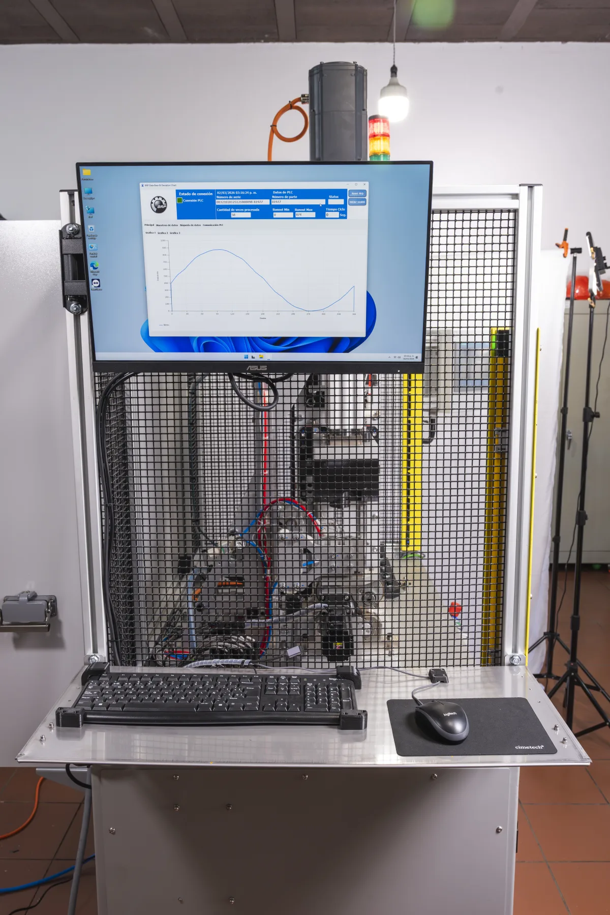 Real-time control software — per-part alignment curve
 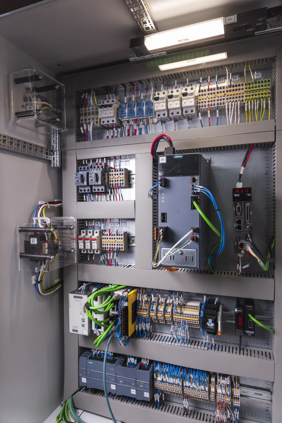 Electrical panel — Siemens PLC + servo drive
 Keyence GT2-A12 LVDT + Kistler 9333A load cell
Independent metrology and force. Servomotor with 1:5 reducer for inertia balance. Two supports with super-precision bearings. Kistler load cell with 50 kN capacity.
Electric ball screw actuator
Servomotor with brake. 20 kN capacity (measured manual operator force: 7.7 kN). Guided system that absorbs bending moments to extend service life.
4 engineering iterations
1:5 reducer on rotation servomotor. Supplier change for pulleys with CMM certification. Anti-bending center supports. LVDT relocation to the base of the rotation mechanism.
Traceability with Keyence SR-X300 reader
Crankshaft Data Matrix read automatically. Local database with: number of times processed, run-out per degree of rotation, applied force, servo position and speed.
Measurement noise from 120 µm to 7 µm — the system now assures
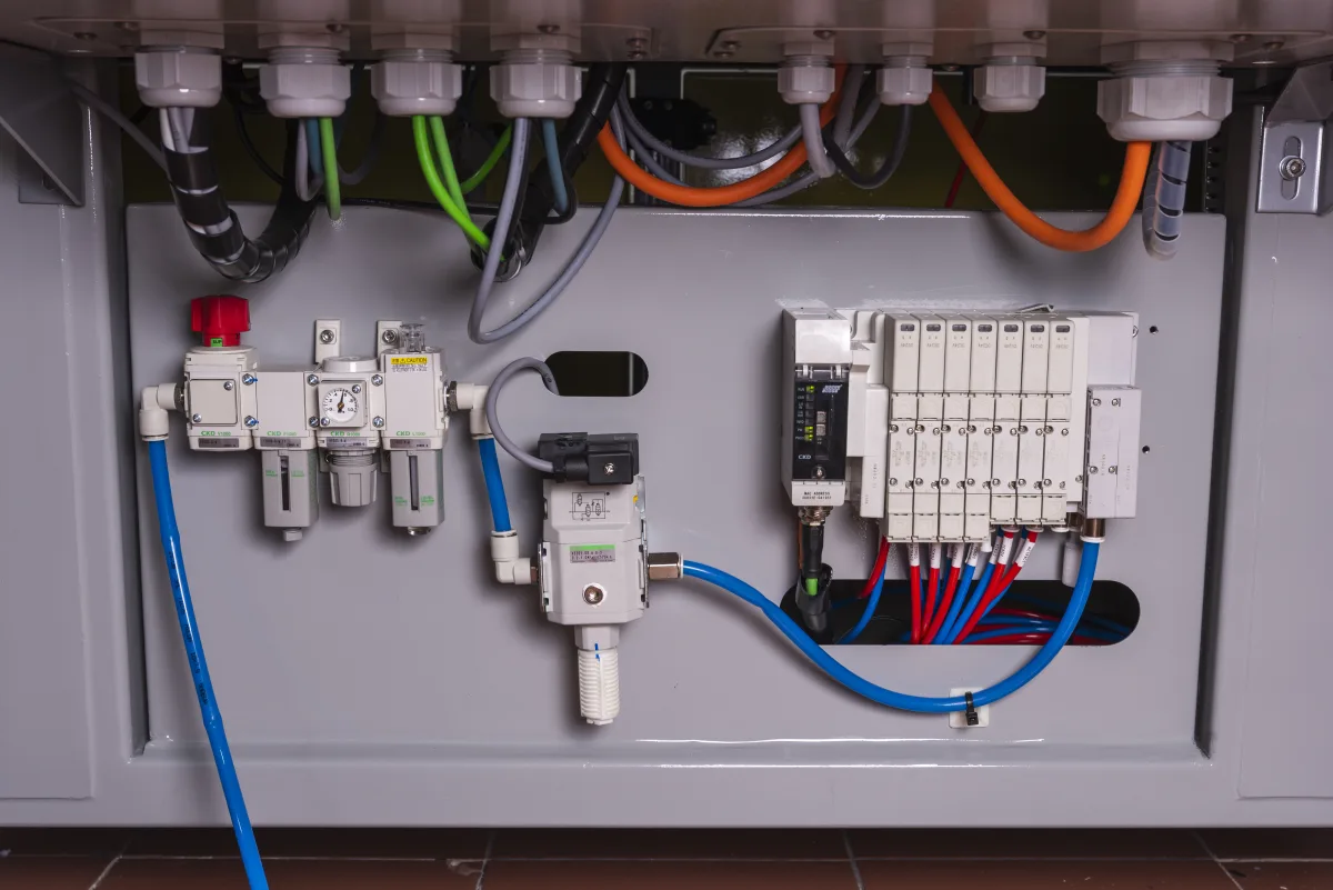 Pneumatic system with CKD valves — integrated precision components
 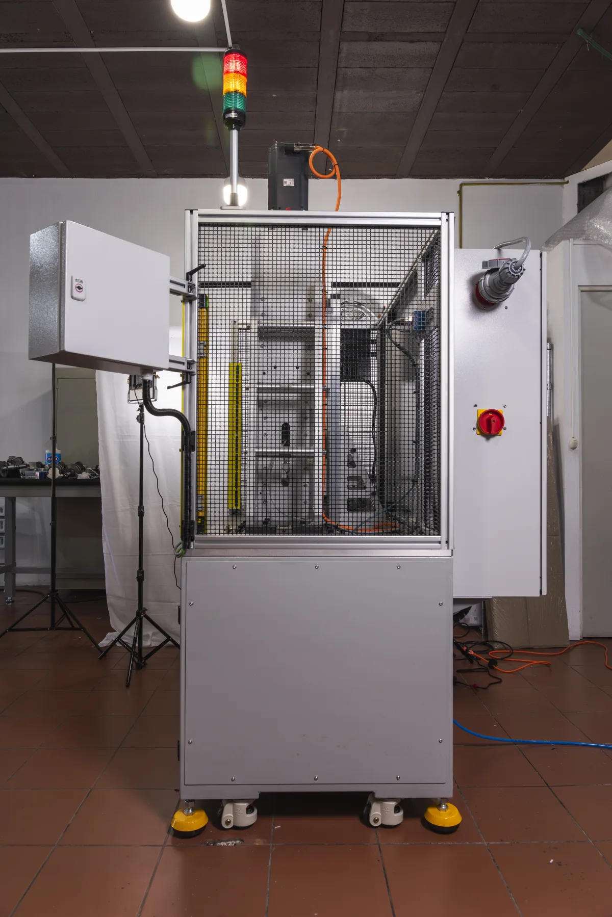 Lübeck Bajío facilities — fabrication and testing in-house
 "Shift-to-shift variability was the real problem. By converting alignment to an automatic process, we eliminated the variability — not the operator's fault."
— Lübeck Engineering, case 03 analysis
We automate it.
Process, not luck.
If you have shift-to-shift variability or operator dependence at critical assembly or measurement points, let's talk diagnostics before proposing a solution.